Overview
CMiC has developed a new web based drawing and specification extraction and upload tool that can upload PDF drawing sets to a user project. The program will OCR the entire set and pull out key details like Sheet Number, Title and Trade. After the user has validated the results - they can publish the sheets to their project. The program will then insert hyperlinks for any detail or elevation callouts in the set automatically. This tool is located in the Drawings and Specs Upload submenu under Document Management in the CMiC Field treeview.
NOTE: The OCR process is only compatible with vector (digital) PDF files. If a rasterized (scanned) PDF file is uploaded, the OCR process may complete with errors, and system generated hyperlinks will not be created. The system generated automatic hyperlinks are only created for the callouts if the drawing set consists of vector (digital) PDF files.
This
Getting Started
The following links will help you get started using the tool:
Security Setup
To access the Drawings and Specs Upload menu item, security setup is required and any custom Treeview will need to be modified to gain access to the screen.
Security Roles; standard Treeview path: CMiC Field > Security > Role Maintenance - Assign Menu Items
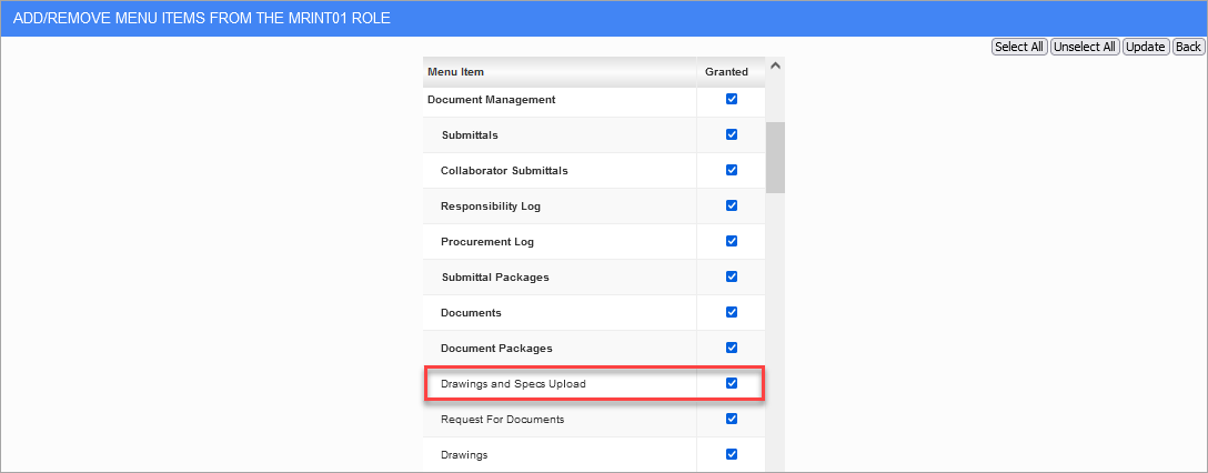
To grant access to the screen, the Drawings and Specs Upload menu item will need to be assigned to the appropriate security role. Locate the security role in the Role Maintenance screen and select "Assign Menu Items" in the drop-down menu. Next, check the 'Drawing and Specs Upload' checkbox under Document Management. Additionally, specifications will only be available if all of the flags for the "Specification Management" document type are checked under the user's project role.
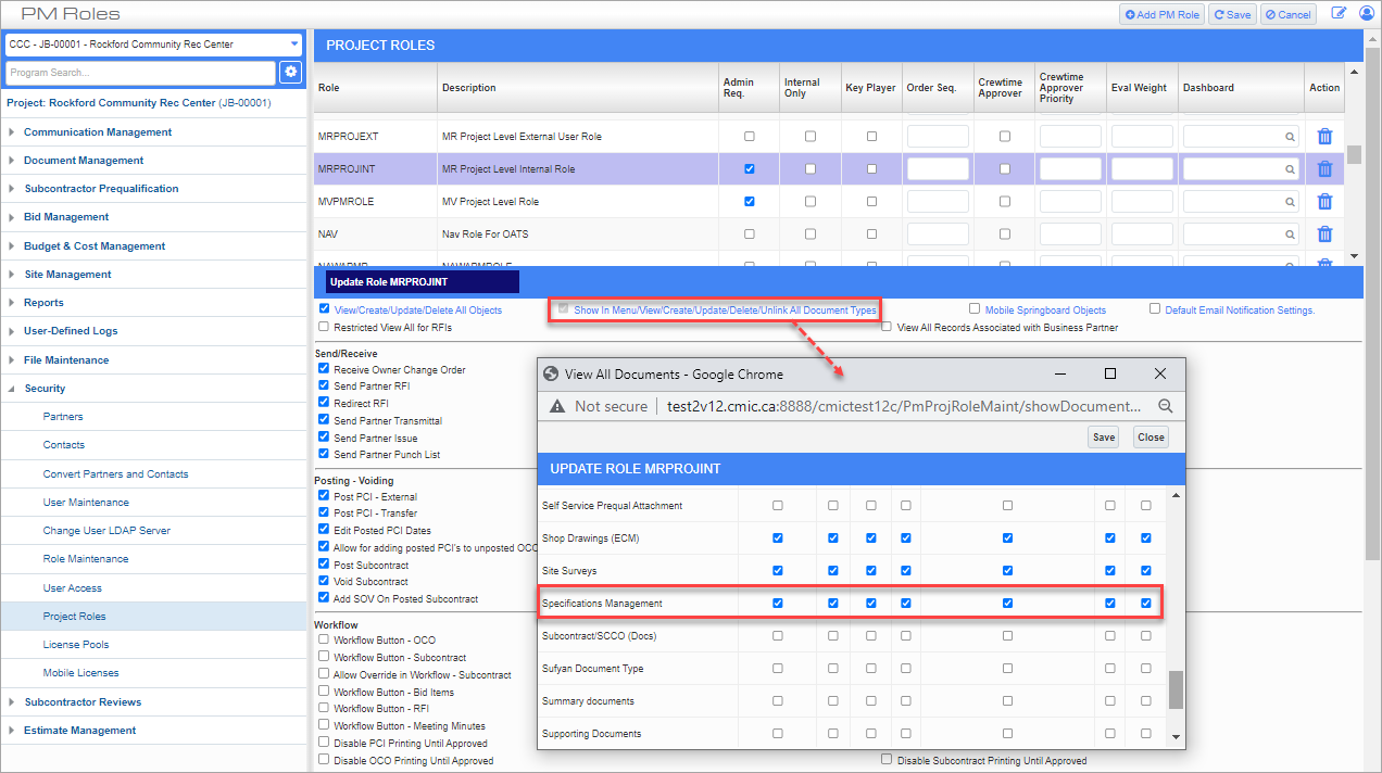
Project Roles; standard Treeview path: CMiC Field > Security > Project Roles
File Naming Convention
Naming your drawing and specification files correctly ensures that files are processed properly. As a guideline, we have compiled a list of allowable characters below.
List of Allowable Characters
- (normal dash and em dash), . (period), )( (brackets), : (colon), ' (apostrophe), " (double quotation), ' (single quotation), , (comma), & ("and" sign), spaces in between (not before or after), _ (underscore). and # (number sign)
NOTE: Sheet number does not allow for “#”.
Upload PDF Drawing or Specification Set
Click the Drawings and Specs Upload menu item to open the screen. Please note that the Drawing and Specs Upload tool only supports the upload of PDF files.
NOTE: If you don't see the Drawings and Specs Upload menu item in the Treeview, ensure that you have completed the Security Setup described in the previous section.
Drawing & Specification Management; standard Treeview path: CMiC Field > Document Management > Drawings and Specs Upload
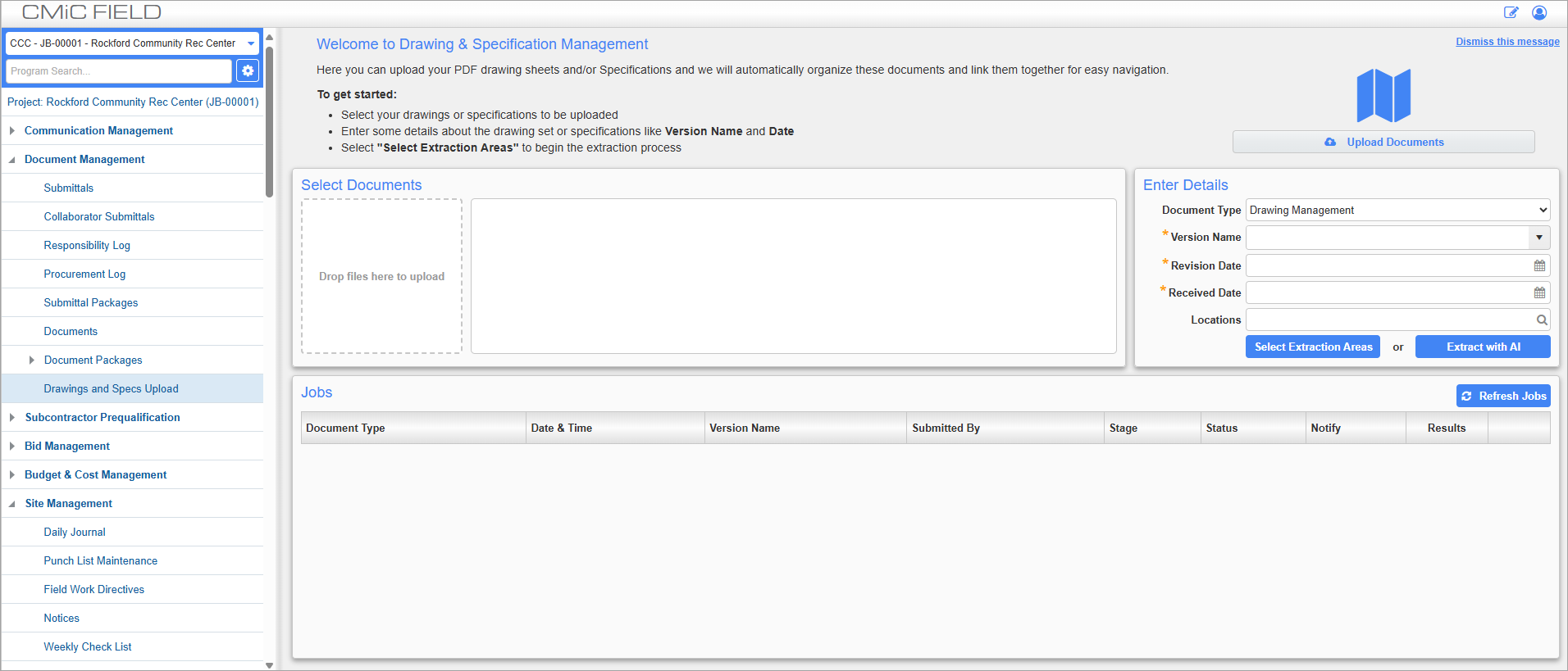
When the screen is first launched, a welcome message is displayed with some basic steps to help new users get started. This message can be closed using the Dismiss this message link to expand the workspace, but the message will be re-displayed with every new browser session.
To upload a set of drawings or specifications, use the [Upload Documents] button or drag and drop a file directly in the box labeled "Drop files here to upload". In the Enter Details panel, select the type of document you are uploading from the Document Type field’s drop-down menu. Selections available are “Drawing Management” and “Specifications”. Next, enter the version name, revision date and received date for the drawings or specs.
NOTE: For drawings with existing annotations, the annotations will not be read/extracted during the upload process. Once the set is uploaded, those annotations will not appear in the drawings and will need to be recreated using the Drawing tool. To preserve existing annotations, we recommend flattening the PDF file before uploading. This process merges all the document layers into single layer, preserving critical annotations such as essential government approval stamps. For information about how to flatten a PDF in Adobe Acrobat, please visit How to flatten a PDF: A step-by-step guide.
One or more drawing or specification sets can be uploaded at the same time if the upload size is within the upload size limit permissible for the server.
Extract Areas
Once the desired document sets have been uploaded, users can manually select the sheet title and sheet name areas or use the AI feature for automatic extraction.
NOTE: The [Extract with AI] button is
Select Extraction Areas (Manual Extraction)
Click the [Select Extraction Areas] button to bring up a window with a view of your document, as shown below.
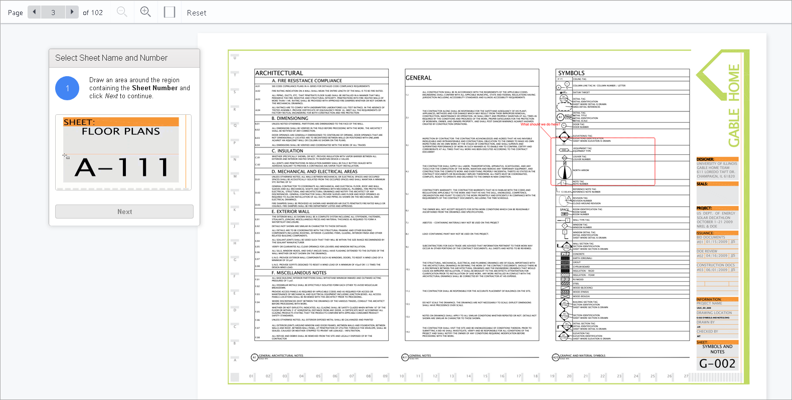
Selecting sheet name and number for a scanned drawing
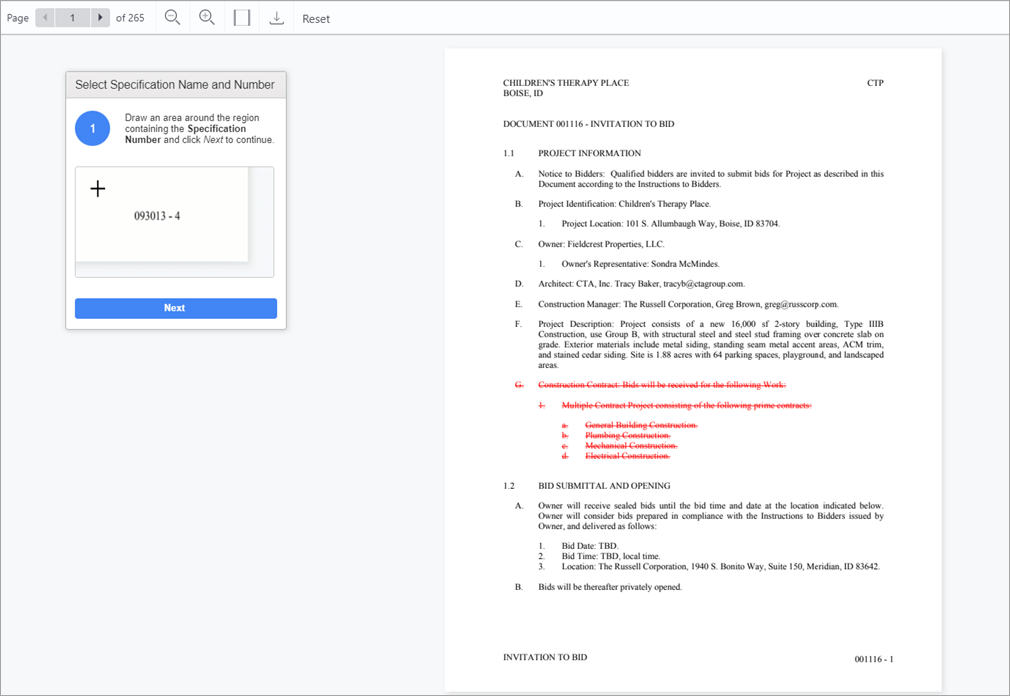
Selecting name and number for a scanned specification
The documents are scanned and then users must select either the Sheet Number and Sheet Name regions (for drawings), or the Specification Number and Specification Name regions (for specifications).
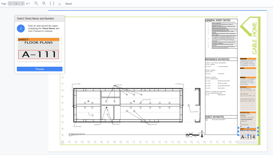
Drawing ready for extraction process
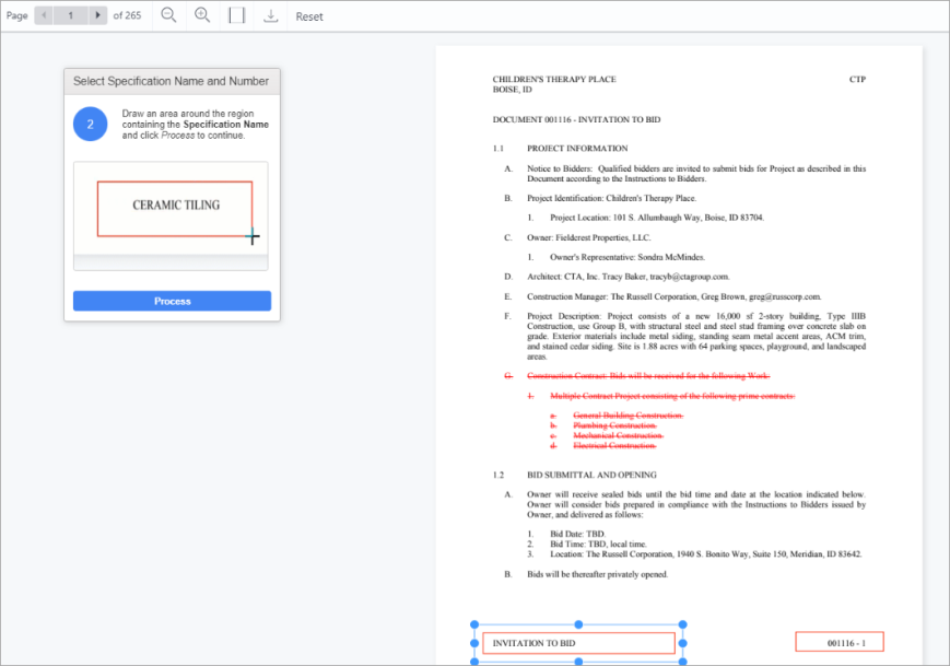
Specification ready for extraction process
Extract with AI (Automatic Extraction)
Click the [Extract with AI] button to automatically extract the sheet title and sheet name without requiring manual input.
NOTE: The Scheduler Log in Enterprise (standard Treeview path: System Data > Utilities > Scheduler Log or Scheduler Log (New)) contains information about any failed AI extraction attempts.
For more information on setting up and extracting with AI, please refer to CMiC Field - Using AI Drawing Extraction.
Extraction Processing
The following pop-up will appear to inform the user that they will receive an email notification once the submitted sheets have had their data extracted. Click [OK] to close the message and return to the Drawing and Specification Management screen.
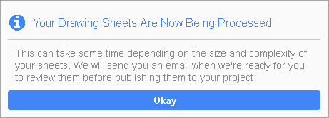
Pop-up window launched to indicate drawing sheets are being processed
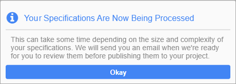
Pop-up window launched to indicate specifications are being processed
Drawing and Specifications Extraction Job Log
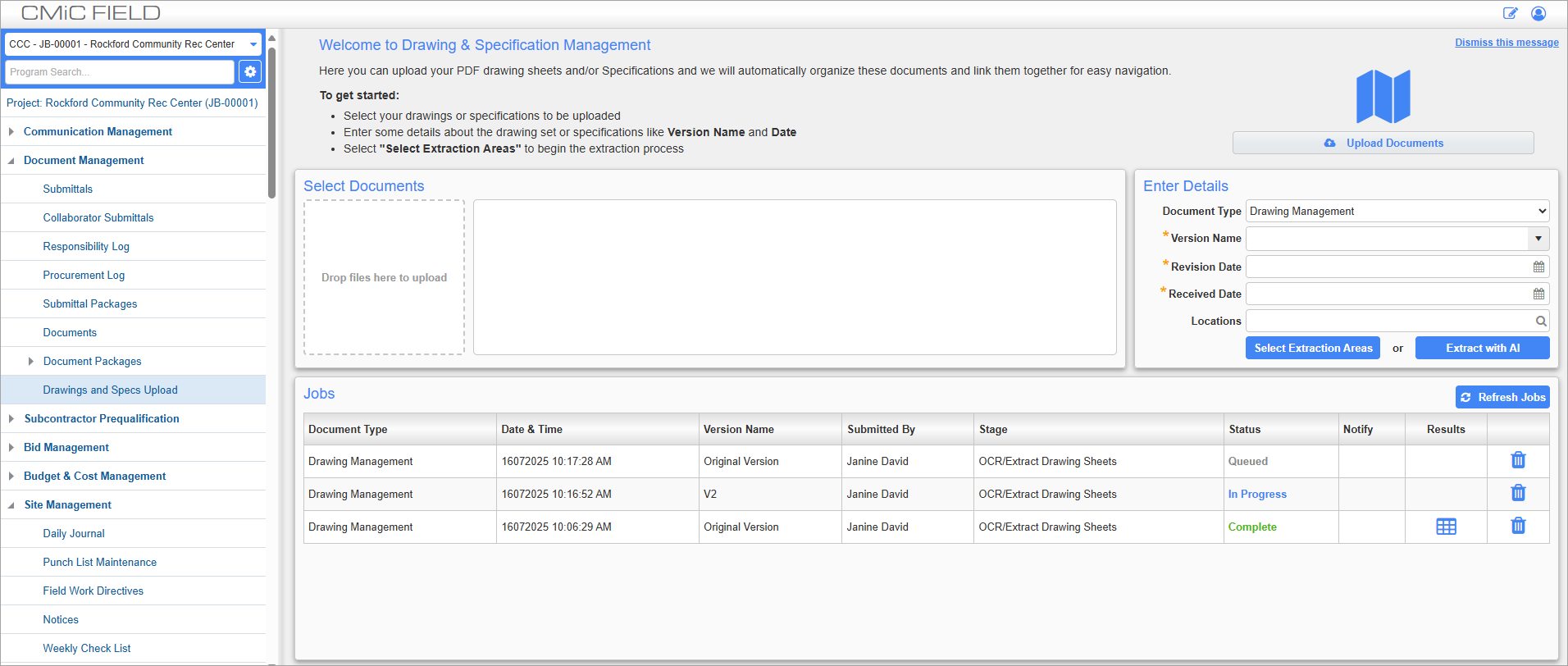
The Jobs section displays all extraction and link generation jobs that are in progress, completed, queued, or failed for the current project.
Document Type
This field shows whether the log entry is for a "Drawing Management" or "Specification" job.
Stage
The Stage column displays the current stage of the job's process. Depending on whether or not a drawing or specification set is being processed, jobs are broken down into the following stages:
Drawings
-
Drawing OCR/Extraction – This is the core process that splits the drawing set into individual sheets and OCRs the Sheet Number and Title.
-
Generating Hyperlinks – This process scans the drawing set and inserts hyperlinks for all detail/elevation callouts.
-
Publishing Drawings – This process takes the extracted drawing sheets and loads them into your project.
Specifications
- Extract Specifications – This is the core process that OCRs the Specification Number and Title.
-
Generating Hyperlinks – This process scans the specification set and inserts hyperlinks for all detail/elevation callouts.
-
Publishing Specifications – This process takes the extracted specifications and loads them into your project.
Status
The Status column displays the current status of the job. The following statuses may be displayed:
-
Complete – Indicates that the job has been completed.
-
Queued – Indicates that the job has been submitted to quartz but not started.
-
In Progress – Indicates that the job is in progress.
-
Warning - Indicates that the core extraction process completed but secondary actions like sending a confirmation email has failed. You should contact your CMiC Admin to review the Job Scheduler log for more details.
-
Failed – This status indicates that the core extraction process failed. You should contact your CMiC Admin to review the Job Scheduler log for more details.
Notify
The Email icon ( ) in the Notify column will only be available after the status is “Completed” for the job. Clicking the icon prompts the user to select contacts/distribution lists.
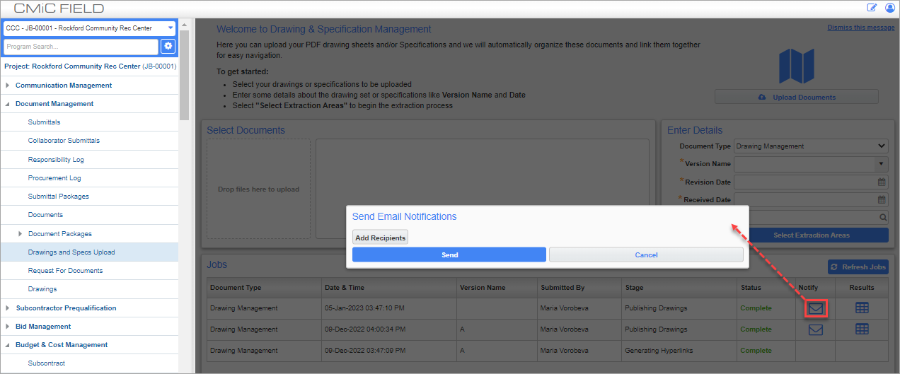
Recipients will receive an email notification containing a 'View Drawings' link that directs them to the corresponding Drawing record in Construct PM.
Results
A drill-down icon (![]() ) exists in the Results column for jobs that have been completed but not yet published. The drill-down launches a window to display the extraction results.
) exists in the Results column for jobs that have been completed but not yet published. The drill-down launches a window to display the extraction results.
NOTE: This information can also be viewed in the Job Scheduler screen.
By default, a completed job can be left unpublished in the job log for up to five days. After five days, if the job remains unpublished, it will be automatically removed. The setting used to control the frequency of this removal process is located in the System Options screen in the System Data module and can be modified if required.
NOTE: The automatic removal process applies to unpublished drawing set uploads and specification uploads.
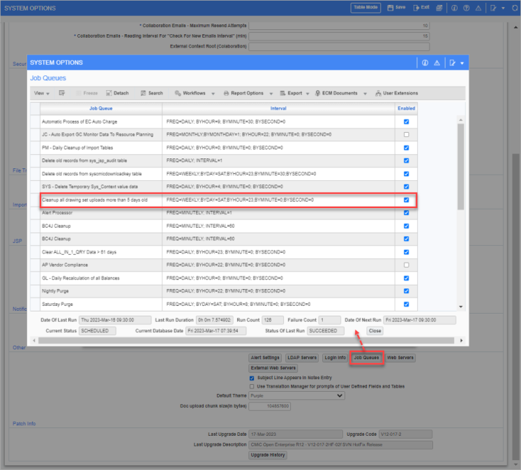
Pop-up window launched from [Job Queues] button on System Options screen; standard Treeview path: System > Setup > System Options – General tab
The pop-up window launched from the [Job Queues] button on the System Options screen contains a specific job used to clean up all drawing set and specification uploads more than five days old. By default, the frequency of this job is set to run weekly but this can be changed to bi-weekly so that it runs less frequently.
The interval line where the job’s default frequency interval is set to run “WEEKLY”:
FREQ=WEEKLY;BYDAY=SAT;BYHOUR=23;BYMINUTE=0;BYSECOND=0
This can be changed to run “BIWEEKLY”:
FREQ=BIWEEKLY;BYDAY=SAT;BYHOUR=23;BYMINUTE=0;BYSECOND=0
When set to bi-weekly, unpublished drawing set and specification uploads will remain in the job log for 14 days before they are automatically removed.
Review Extraction Results
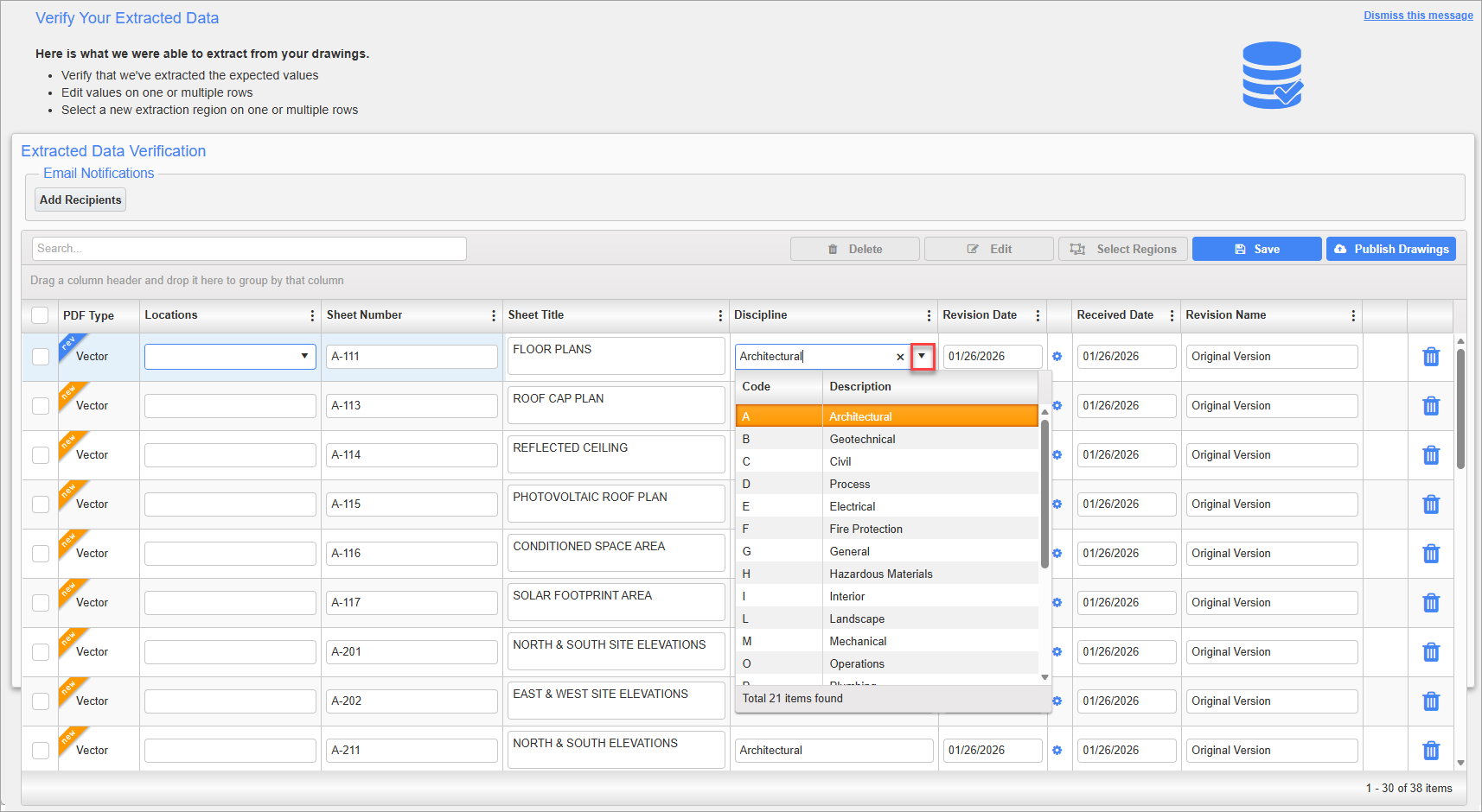
An example of Extracted Data Verification Grid
On the Extracted Data Verification grid, the user can select a new Extraction Region for a selected sheet or specification or carry out other clean-up activities.
The “Discipline” and “Sheet No.” columns will be displayed for drawings, and the “Division” and “Spec Number” columns will be displayed for specifications. The "PDF Type" column will also be displayed for drawings to indicate if the PDF sheet is "Vector" (i.e., PDF sheet is a Vector file) or "Image" (i.e., PDF sheet is a rasterized image).
NOTE: The Discipline field (previously called Trade) is automatically populated during the OCR process based on the prefix of the sheet numbers, as defined in the Discipline Maintenance screen. This field can still be edited manually using the available drop-down menu. Refer to CMiC Field - Discipline Maintenance for more details.
Email Notifications
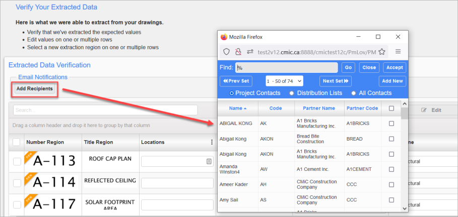
[Add Recipients] – Button
Pressing the button [Add Recipients] allows users to send out I/O emails to selected contacts and/or distribution lists, after new drawings, specifications or revisions have been published to the Drawing or Specification Set.
Batch Edit
Edit
![Pop-up window launched from [Edit] button in a drawing extraction](../../../../../Resources/Images/CMiC_Field/CMICFIELD_DrawingUpload_BatchEdit.png)
Pop-up window launched from [Edit] button in a drawing extraction
NOTE: The field names displayed in the Batch Edit pop-up window depend on whether the screen is launched from a drawing or a specification extraction.
Make changes directly to an individual record (sheet or specification) in a single row or use the checkboxes to select multiple rows (sheets or specifications) to perform mass editing (Batch Edit) on a number of selected records at once. Batch Edit also offers "Find and Replace" for/by a given string.
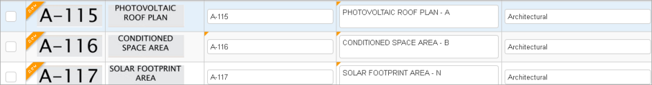
A small yellow triangle in the upper-left corner of a field indicates individual unsaved edits.
Delete

Delete an individual sheet or specification using the Trash Bin icon ( ) on a record's row, or use the checkboxes to select multiple records at once for mass deletion.
If an attempt is made to delete records and any unsaved changes exist, an alert will be issued, as shown in the screenshot above.
Duplicate Sheet and Spec Numbers Not Allowed

Duplicate sheet and spec numbers are not allowed. If an attempt is made to publish drawing or specification sets with duplicate sheet numbers, a message will be displayed, as shown in the screenshot above.

On refreshing the screen, the duplicates will be highlighted by the Duplicate ( ) icon.
Sort, Group By
Sort functionality can be used to sort records in ascending or descending order and Group By can be used to arrange similar records into groups.
[Save] – Button
Use this button to save any changes.
[Publish Drawings] – Button
Use the [Publish Drawings] button when all changes are committed and ready to be published to the project.
Specification Extraction
While the specification extraction and publishing process is similar to the drawing extraction process, there are a few differences to the Batch Edit functions and the extraction screen layout.
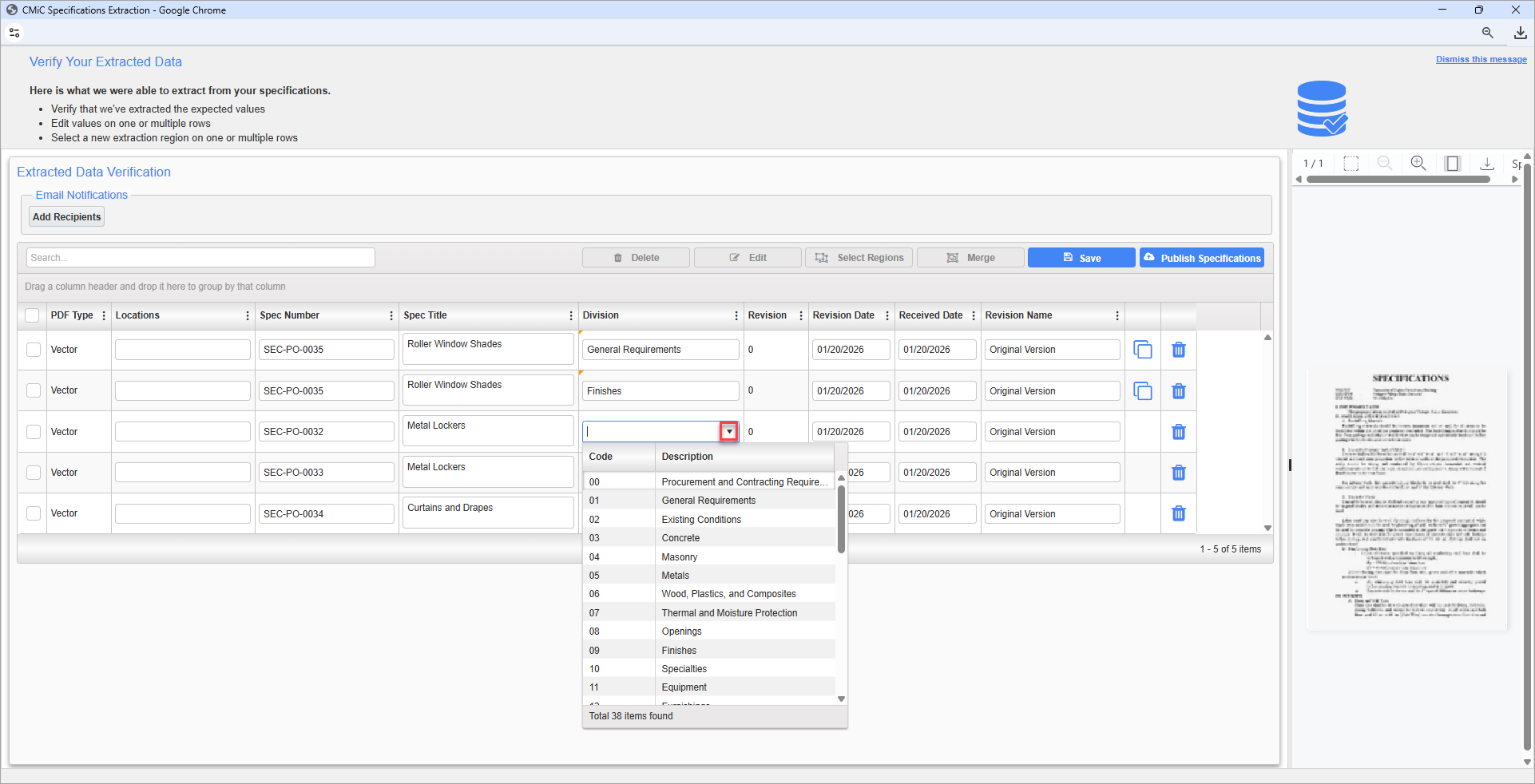
NOTE: The Division field is automatically populated during the OCR process based on the first two digits of the Spec Number. It can be edited using a drop-down menu. The options available in this field are system-defined and are not tied to a maintenance screen. It is not possible to add new divisions or modify the system-defined values in the drop-down.
Edit – Button
![Screenshot of Pop-up window launched from [Edit] button in a specification extraction](../../../../../Resources/Images/CMiC_Field/CMICFIELD-Specification-Extraction_3.png)
Pop-up window launched from [Edit] button in a specification extraction
The field names displayed in the Batch Edit pop-up window depend on whether the screen is launched from a drawing or a specification extraction.
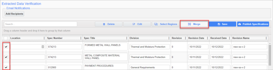
[Merge] – Button
The merge functionality is unique to the specification upload process and allows users to merge multiple specification documents into a single document. Users first select the specification documents they would like to merge with the checkboxes, and then click on the [Merge] button in the toolbar.
Users are then prompted to confirm that they want the selected specifications merged with the following pop-up. Clicking [OK] will merge the selected specifications.
![Screenshot of Pop-up window launched from [Merge] button in a specification extraction](../../../../../Resources/Images/CMiC_Field/CMICFIELD-Specification-Extraction_2_501x127.png)
Pop-up window launched from [Merge] button in a specification extraction
Document Split
The document split functionality is used to split a large specification document into multiple smaller documents. Once extraction is done, specification documents can be displayed on the right-hand side of the Spec validation screen by clicking on a particular spec that user wants to split.
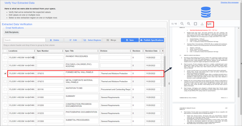
The document view pop-up launched from clicking target specification
Documents are split by scrolling through the pages of the document until the desired page is in view, then clicking on the [Split] button at rightmost side of the top panel. Once the user confirms the decision to split the document using the pop-up, the document will be split into two parts and appear as two separate specification documents.
![Screenshot of Pop-up launched when [Split] was clicked.](../../../../../Resources/Images/CMiC_Field/CMICFIELD-Specification-Extraction_5_493x114.png)
Pop-up launched when [Split] was clicked.
Users can save and publish the specifications after.
NOTE: Users should change the Spec Number field value for the users so that they do not have Duplicate Spec Numbers.
[Publish Specifications] – Button
Use the [Publish Specifications] button when all changes are committed and ready to be published to the project.
Publish Document Set
Drawings
When the [Publish Drawings] button is clicked, an initial message is displayed which indicates that the drawings are being published. Once completed, a second message is displayed to indicate the drawings have been successfully published to the project.
Published records are located in the Drawing Management documents folder. Thumbnails of PDFs can be viewed from this folder.
Documents/Drawings Log
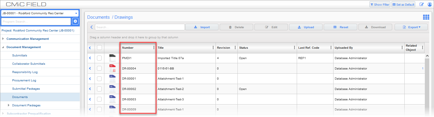
Documents; standard Treeview path: CMiC Field > Document Management > Documents > Drawings
We recommend that the first column in the Drawings log be the ID number (i.e. PMD_ID). This will avoid triggering any errors or unexpected results when downloading documents. The order of the columns is customized in the Log Builder screen.
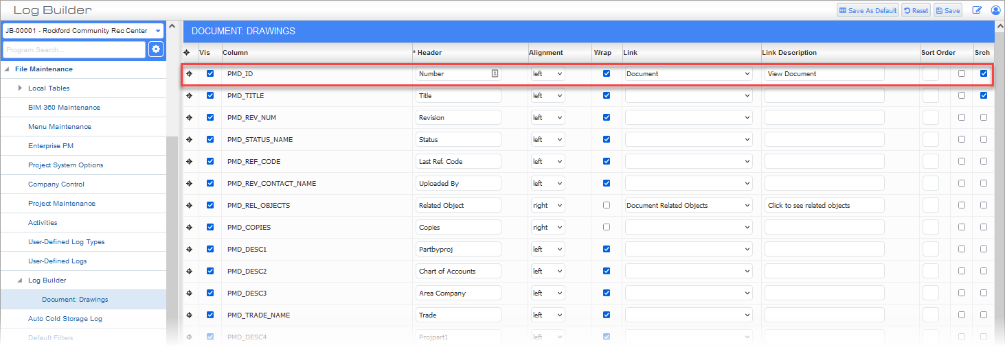
Log Builder; standard Treeview path: CMiC Field > File Maintenance > Log Builder
In the Log Builder screen, open the Drawings log and ensure that the PMD_ID column is located at the top of the log, as shown in the screenshot above.
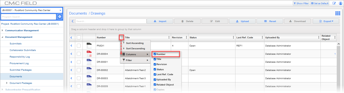
Documents; standard Treeview path: CMiC Field > Document Management > Documents > Drawings
Users can always hide the column, if they prefer for it to remain hidden in the Drawings log. To hide/unhide the column, press the Edit Column Settings icon ( ) to show the menu in the above screenshot. Hover over the Columns menu item and check/uncheck the column’s checkbox, depending on whether the column should be visible in the log. Hiding the column using this method does not remove it from the log, it only prevents it from being displayed.
Specifications
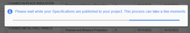
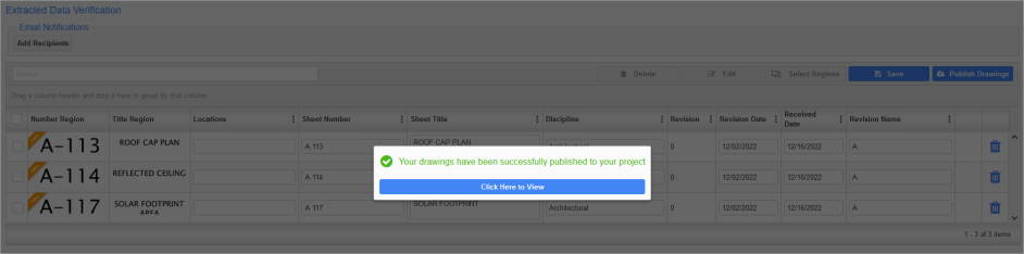
When the [Publish Specifications] button is clicked, an initial message is displayed which indicates that the specifications are being published.
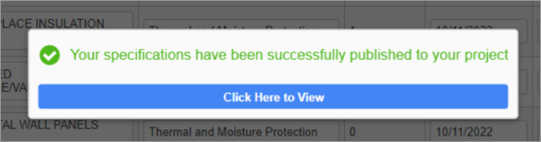
Once completed, a second message is displayed to indicate the specifications have been successfully published to the project.
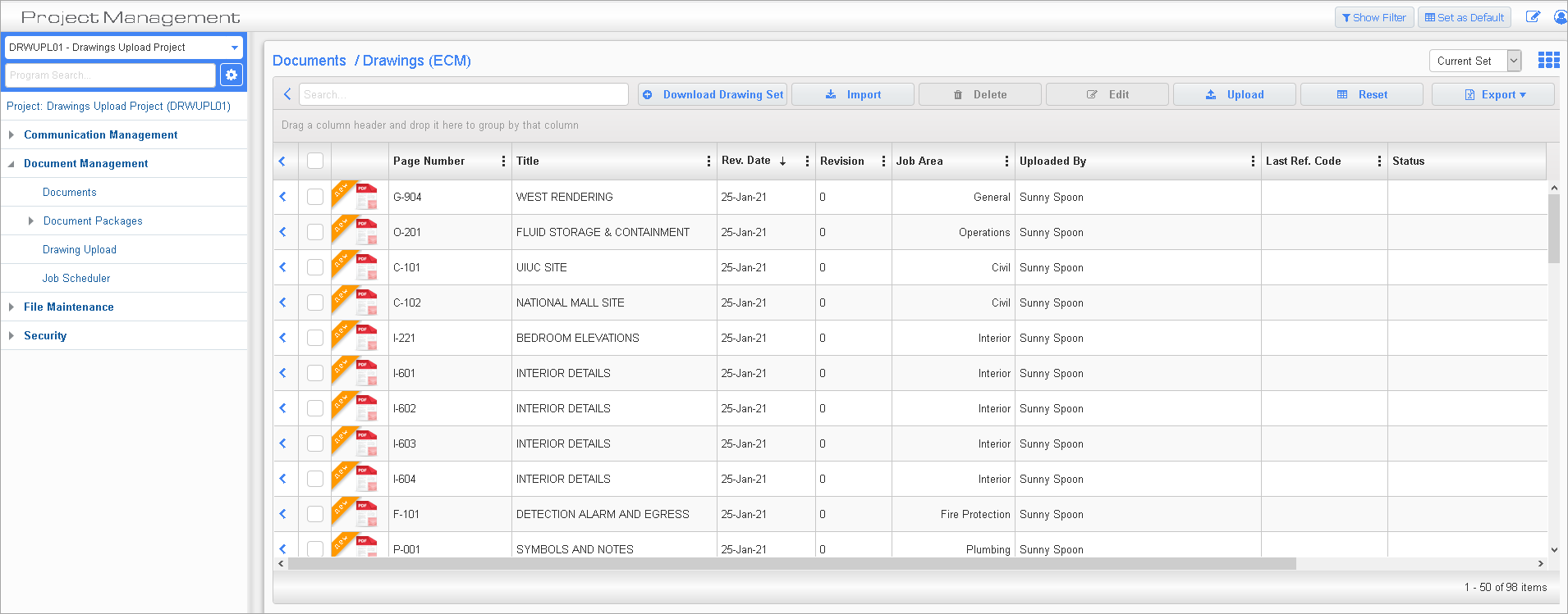
Documents/Specifications Management Log
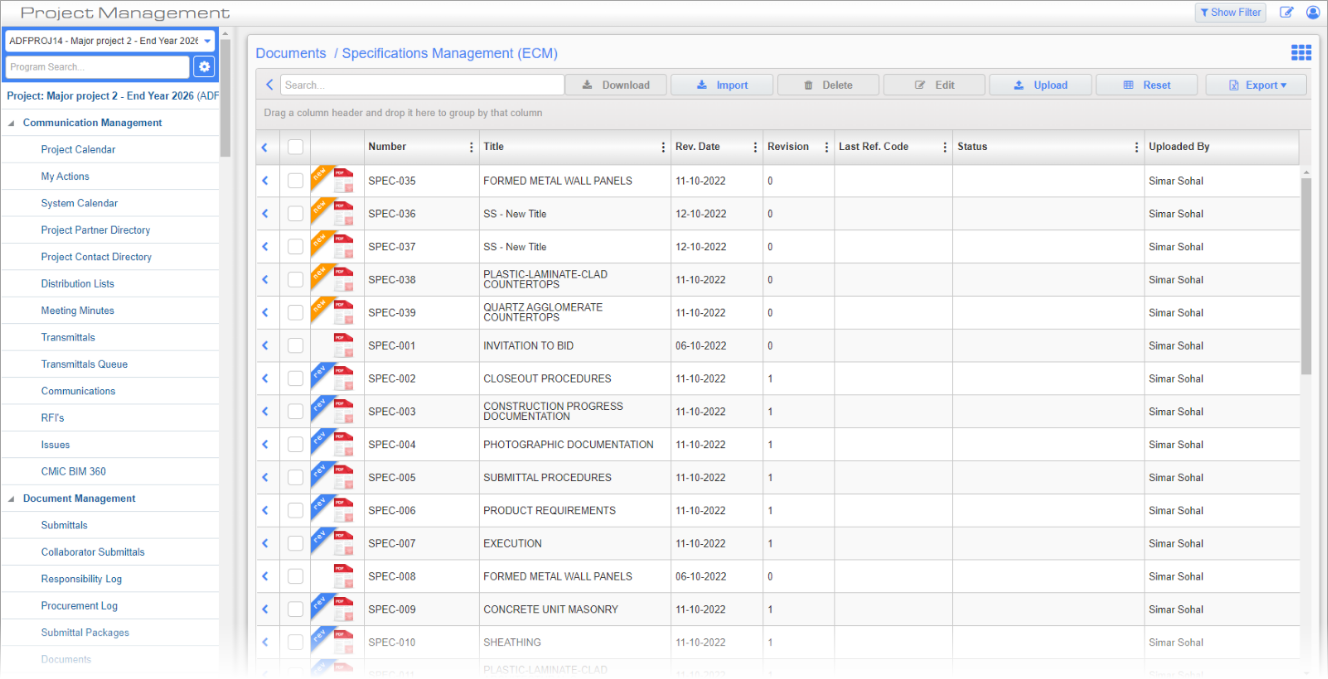
Published records are located in the Specifications Management (ECM) documents folder. Thumbnails of PDFs can be viewed from this folder.
Email Notification of Sheets Processed and Links Generated for Drawing Set and Specification Set
After the drawings or specifications have been uploaded to the project, another notification email is sent to the current user's email address.
Drawings
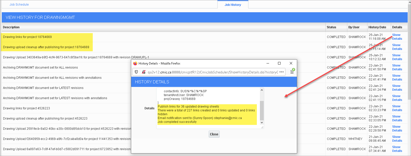
ADMIN PRO-TIP: If no email is received, check the Job History tab of the Job Scheduler screen for the DrawingMgmt job.
For drawings the notification email indicates how many sheets were processed and how many hyperlinks were generated out of those sheets. These hyperlinks are automatically inserted when the drawings are published and includes new sheets as well as revised sheets.
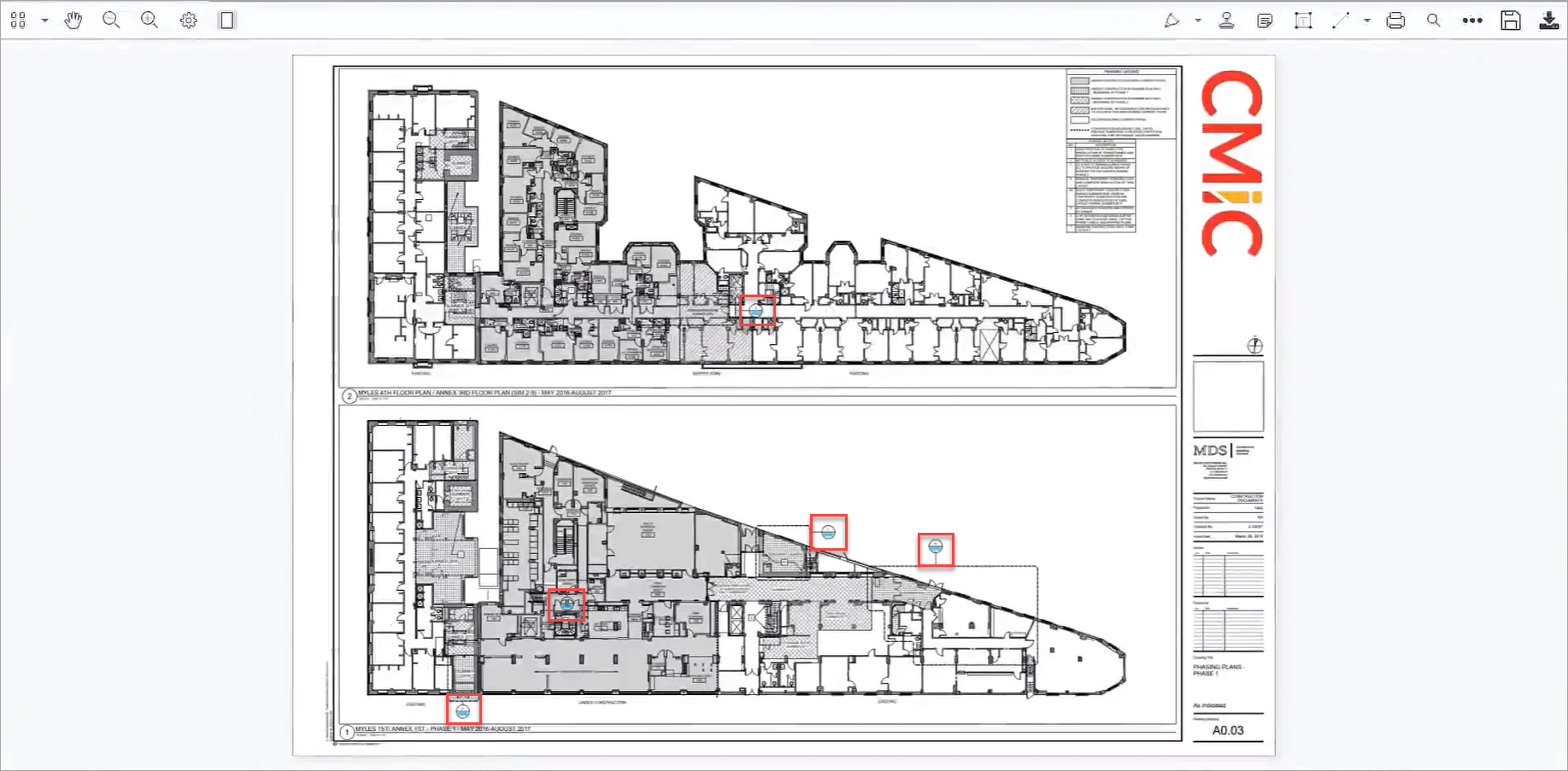
Sample Drawing with Links Automatically Generated
To review the links, open up a drawing in the Drawing Management documents folder. The screenshot above shows an example of a drawing with links highlighted in red.
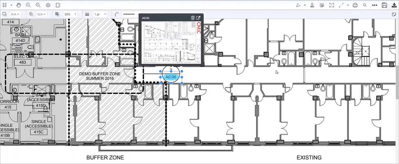
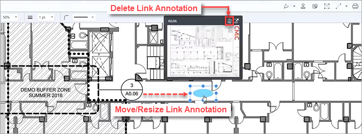
Link Provides Preview of Linked Sheet
Clicking on a link provides a pop-up preview of the linked sheet, as shown in the screenshot above.
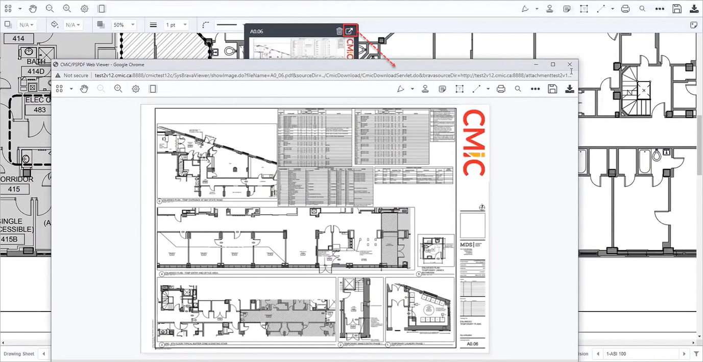
From here, the user can either click on the pop-up preview to open the linked sheet, or click on the Launch icon ( ) in the upper right-hand corner of the pop-up preview to open the linked sheet in a new window. This new window can be moved onto a second monitor, allowing both sheets to be open and viewed side by side.
Specifications
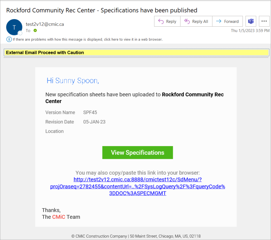
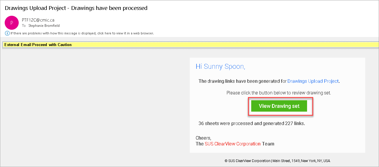
For specifications the notification email indicates the version name, revision date and location of the specification. To review the links, either click the [View Specification] button through the user's email, or open up the specification in the Specification Management documents folder.
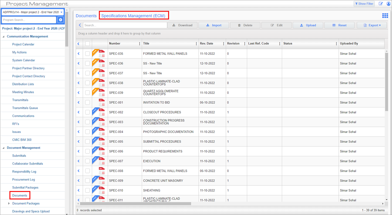
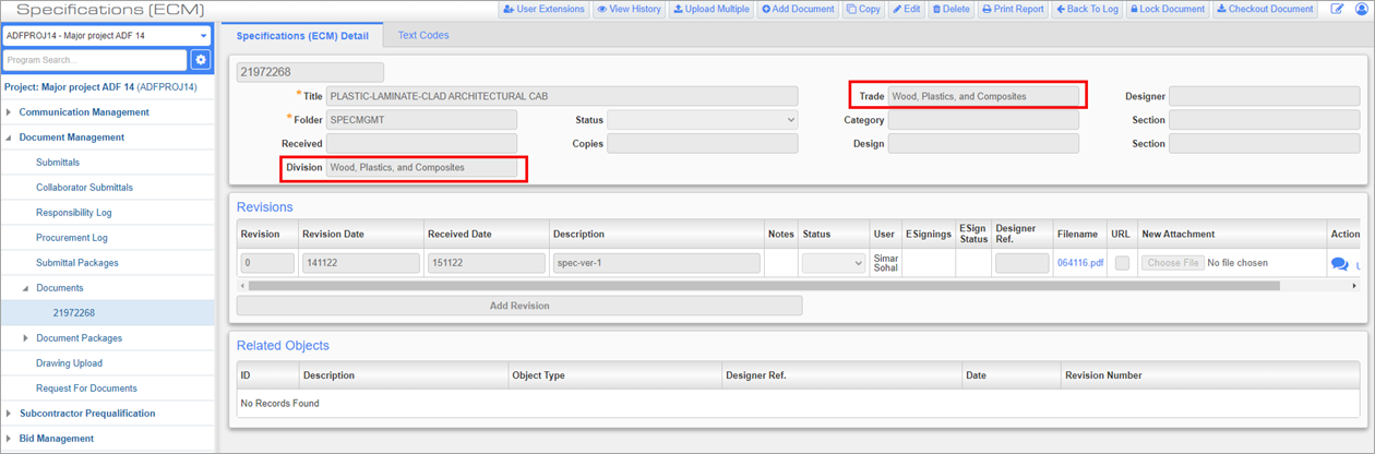
Once the specifications are published, when one of the records is opened, the ‘Trade’ field should display the value same as the ‘Division’ field value in the header section.
Moving / Resizing and Deleting Link Annotations
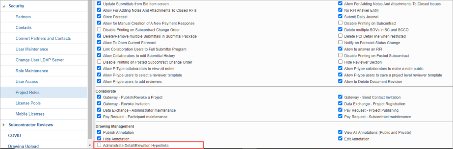
Moving, resizing, and deleting annotations is reserved for those users with the following project role privilege: 'Administrate Detail/Elevation Hyperlinks'. This new project role is located under the Drawing Management section of the Project Roles screen.
Administrate Detail/Elevation Hyperlinks - Checkbox
Project Roles; standard Treeview path: CMiC Field > Security > Project Roles
Check the 'Administrate Detail/Elevation Hyperlinks' project role to allow users to move, resize, and delete link annotations.